TECHNICAL SPECIFICATIONS
Aluminium Profile Modular System consisting of different type of modules.
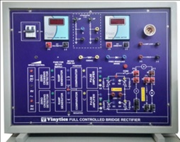
Educational Bench Top Model with schematic / block diagram of the test circuit engraved on the panel.
Test points & measurement points brought out
and connected to 2mm plastic & BT15/30 terminals circuit setup for testing through
in reconnections of patch cards.
Complete illustrated manual covering brief theory of Equipment along with technical details and experimental procedures,
Connection diagrams will be supplied with experimental set up.
Technical Specifications:
1) Digital Meters: Voltage (0-300V) & Current Measurement (0-10A)
2) Digital RPM counter
3) Double Pole MCB
4) LED Indicators
5) D.C. MOTOR:
Type: DC Motor, separately excited, screen protected, horizontal foot mounted, fan cooled, Capacity: 1 HP,Winding: Shunt wound, R.P.M.: 1500, Volts. : 230,Insulation:
Class ‘B’, Armature and field sockets brought out to connect to the panel
6) FIRING CIRCUIT:
Line Synchronizing Op-Amp based triggering circuit
Firing Pulse Generator Digital type
Potentiometer used to vary the triggering circuit
Pulse output terminals
1:1 Pulse Transformer 1 KVA
Step Down Transformer Firing Circuit.
7) POWER CIRCUIT:
Four SCR’s (600V/12A)
Suitable RC Snubber Circuit
Free Wheeling Diode
8) LOAD
Consist of resistive load (100Wx1)
Lamp Holder
Lamp 250 Volts or
Inductive Load
9) 1:10 Attenuator for RRO
10) Isolated 220V AC for CRO
11) Field & armature terminals for DC shunt motor
12) Uncontrolled DC output 220V for field voltage of DC motor
Address List
- 12, Truck Market, Opp. R.K. Hospital, Near Mother Dairy Red Light , Pandav Nagar, Delhi-110092
-
+91 9899899166
+91 9871600331
+91 9868039427 -
vinyticsindia@gmail.com
www.vinytics.in